Vintage 1946 Sonora AM Radio Restoration – 06 – Re-CAPing the Radio
Vintage 1946 SONORA AM RADIO RESTO-MOD PROJECT
Re-CAPing the Radio (Replacing Capacitors):
While I was adding coats of Tung Oil to the cabinet, I started working on assessing what I was going to do to replace the old capacitors in the radio. It is a good idea to be VERY methodical about your approach to this and make sure you are precise with identifying the old capacitors. Make sure you document where they are located, any polarity they may have, and what the values and voltages are that are marked on them. So, I first removed all of the vacuum tubes one by one first to keep them from getting damaged. As I removed them, I identified them, recorded their location and the numbers on them, and then put them in a safe place until I was ready to work with them. Most of these are fragile and some are made of glass an you don’t want to be bouncing them around or even worse, breaking them. I also removed the screws that held the speaker in place, desoldered the wires attached to the speaker, and put the speaker in a safe place to keep it from getting damaged as well.
The old capacitors were installed in a way that made them hard to read the values on them in the location they were in so I decided to make a drawing of the layout of them all, remove them one by one, and write down the critical information about each one as they were removed. I made sure that I checked and double checked the Capacitance and voltage values which is usually stated in microfarads (MFD) and “Working Volts” (WV). I also paid close attention to the way the capacitor was removed from it’s location and looked to see if there were any polarity markings (+/-) to make sure that I marked the proper polarity on the drawing and marked the capacitor as an “Electrolytic” capacitor as well.
And here is a little tip in replacing capacitors like this in an old radio. When you cut the old capacitor out of the circuit, leave a little bit of the lead so that you can use the extra to make a loop to solder the new capacitor to.
Here is a list of the capacitors that were removed along with the values.
| Cap # | ORIGINAL CAPACITOR VALUES | REPLACEMENT CAPACITOR VALUES |
| 1) | .09 MFD – WV DC 200 | .04µF + .05µF (in parallel) 400V |
| 2) | .05 MFD – WV DC 400 | .05µF 600V |
| 3) | .1 MFD – WV DC 200 | .1µF 600V |
| 4) | .05 MFD – VDC 200 | .05µF 600V |
| 5) | 6 MFD – WV 150 (Electrolytic) | 8µF 200V Electrolytic |
| 6) | .005 MFD – VDC 600 | .005µF 600V |
| 7) | .05 MFD – VDC 600 | .05µF 600V |
| 8) | .0005 MFD – WV DC 1000 | 500pF 3000V |
| 9) | .003 MFD – WV DC 600 | .0033µF 600V |
| 10) | .02 MFD – DC WV 400 | .022µF 630V |
| 11) | .015 MFD – WV DC 400 | .015µF 400V |
| 12) | .01 MFD – WV DC 400 | .01µF 600V |
| 13) | 40 MFD – 150 WV (Electrolytic) 40 MFD – 150 WV (Electrolytic) |
47µF 200V Electrolytic 47µF 200V Electrolytic |
Note 1: Capacitor 13 is actually 2 capacitors in one package and can be replaced with two separate capacitors.
Note 2: MFD stands for MicroFarads, today it is represented by Mu or Micro symbol µF. So a .05 MFD and a .05 µF capacitor are the same thing.
Note 3: pF is PicoFarads (you can convert MicroFarads to PicoFarads by multiplying by 1,000,000)
You will notice that the values are not exactly the same and the voltages are not the same either for the replacement capacitors that I chose to use!
Capacitors can be replaced with a value that is higher (not lower) and within a certain percentage of the original. The voltage also can be higher but cannot be lower than the original! Also, notice that I used two capacitors to replace the first capacitor listed. When placed in parallel, the capacitance value is added up. But make sure the voltage rating for all capacitors done this way are higher than the original. Once I had all the capacitors replaced, I double checked everything and could now turn my attention to the chassis and tubes.
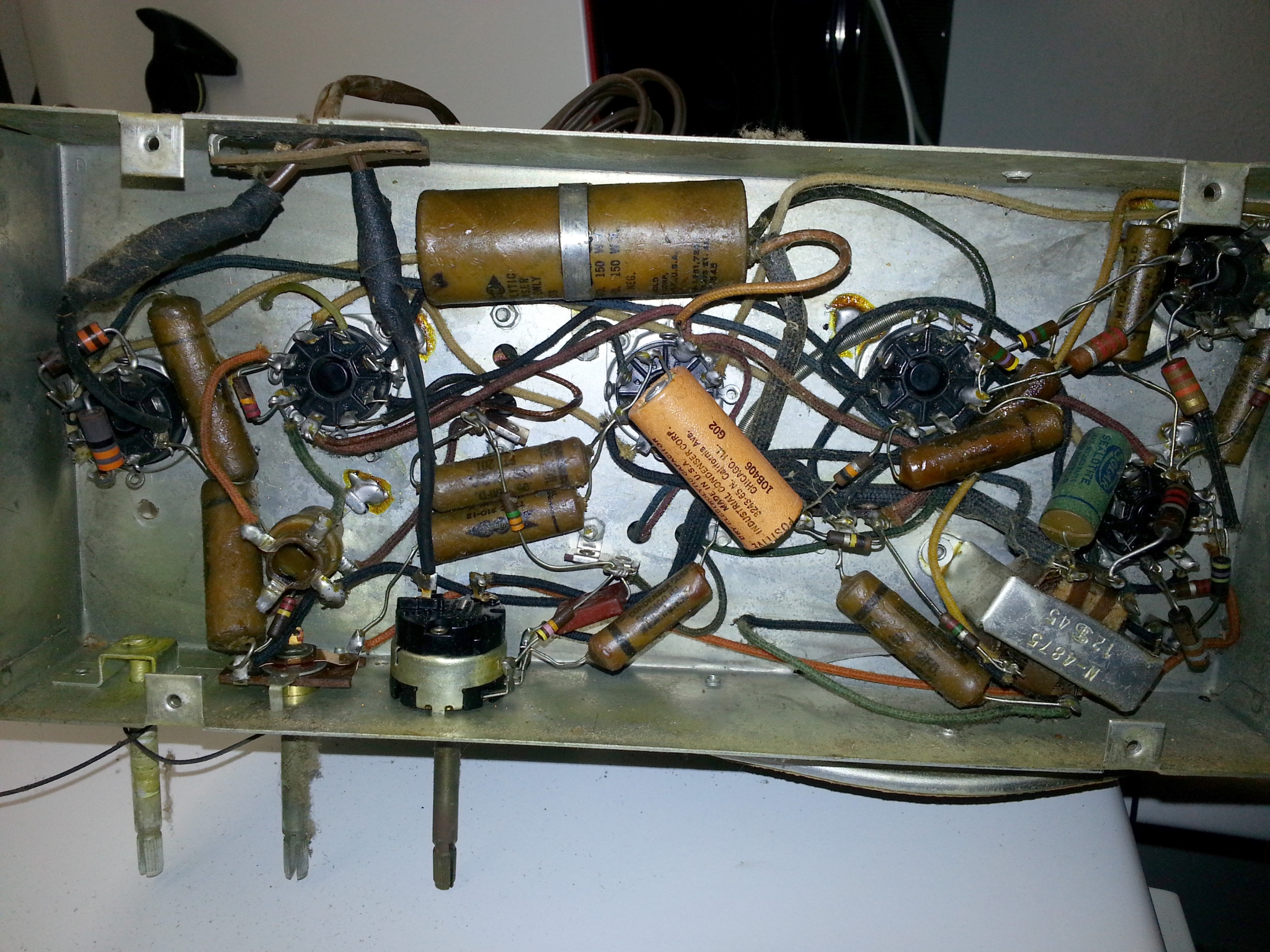
Here is a photo of the electronics before replacing anything. The capacitors are the components that are mostly in long cardboard tubes with a wax coating on them. The long cylinder looking things.
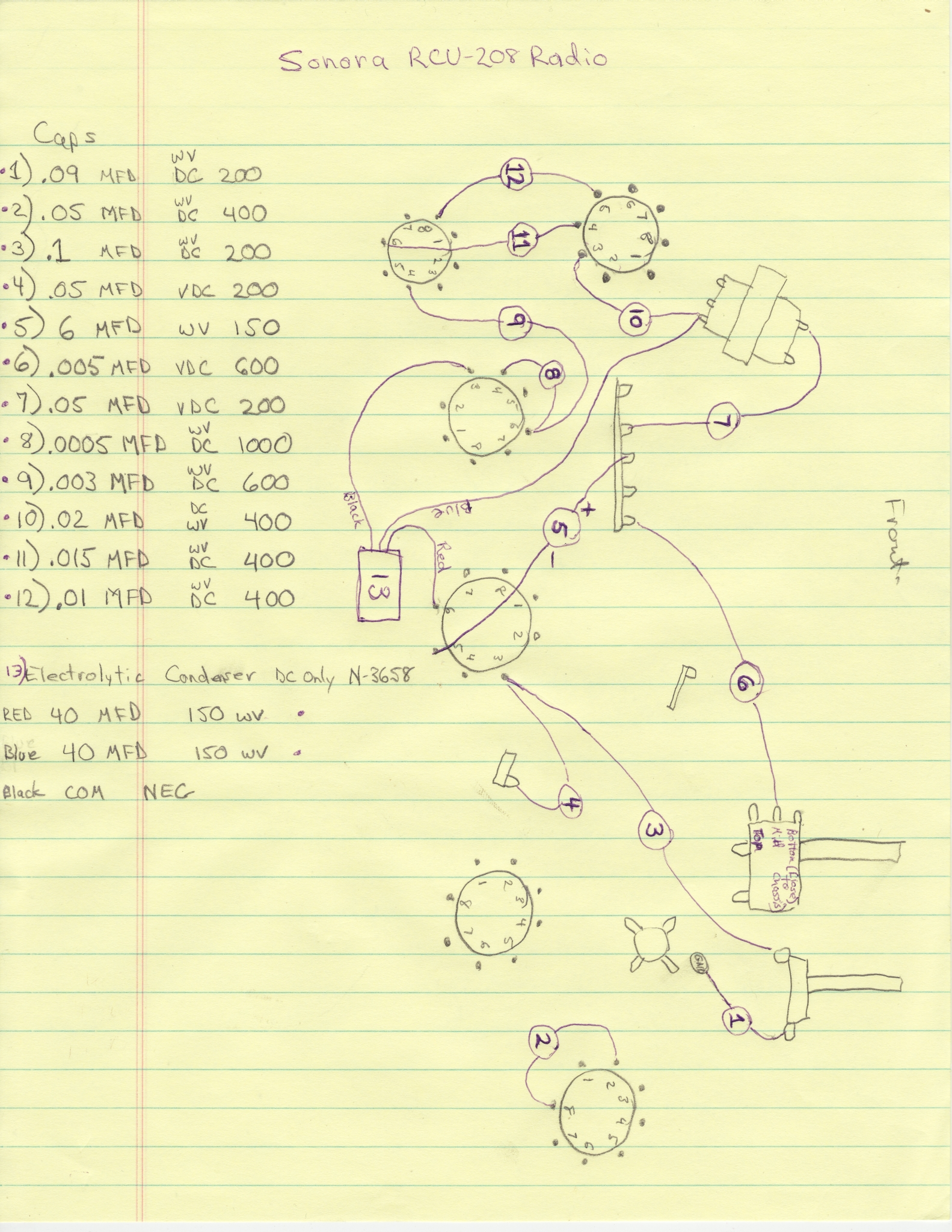
As I removed each capacitor, I made a “map” of where it came from and noted the values like this.
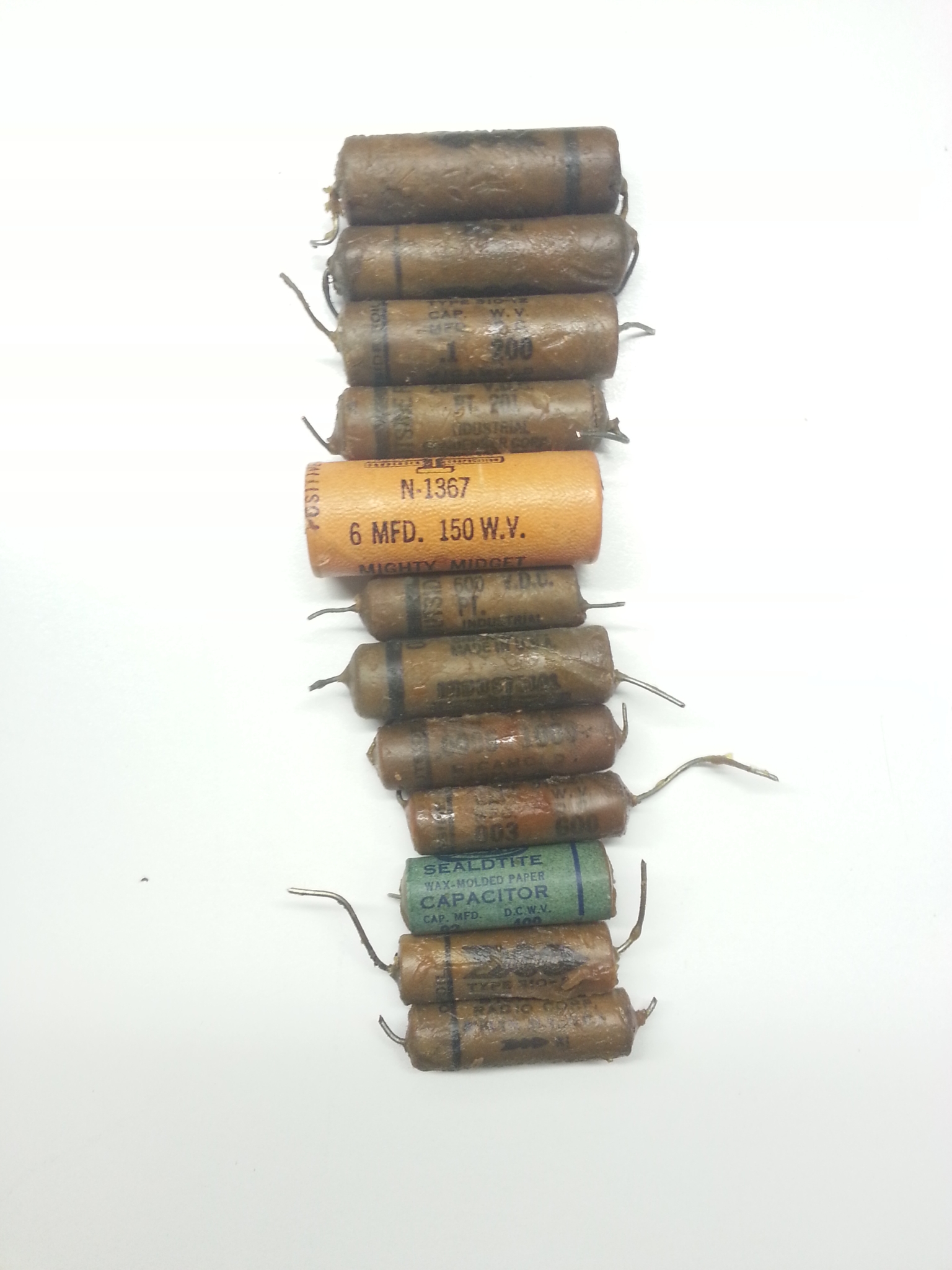
Here is what it looked like with all of the capacitors removed (with the exception of the one big double capacitor that you see towards the bottom of the image:

Old Caps:
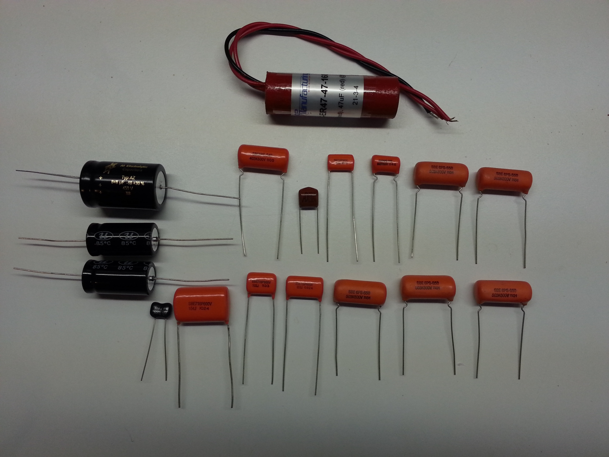
New Caps:
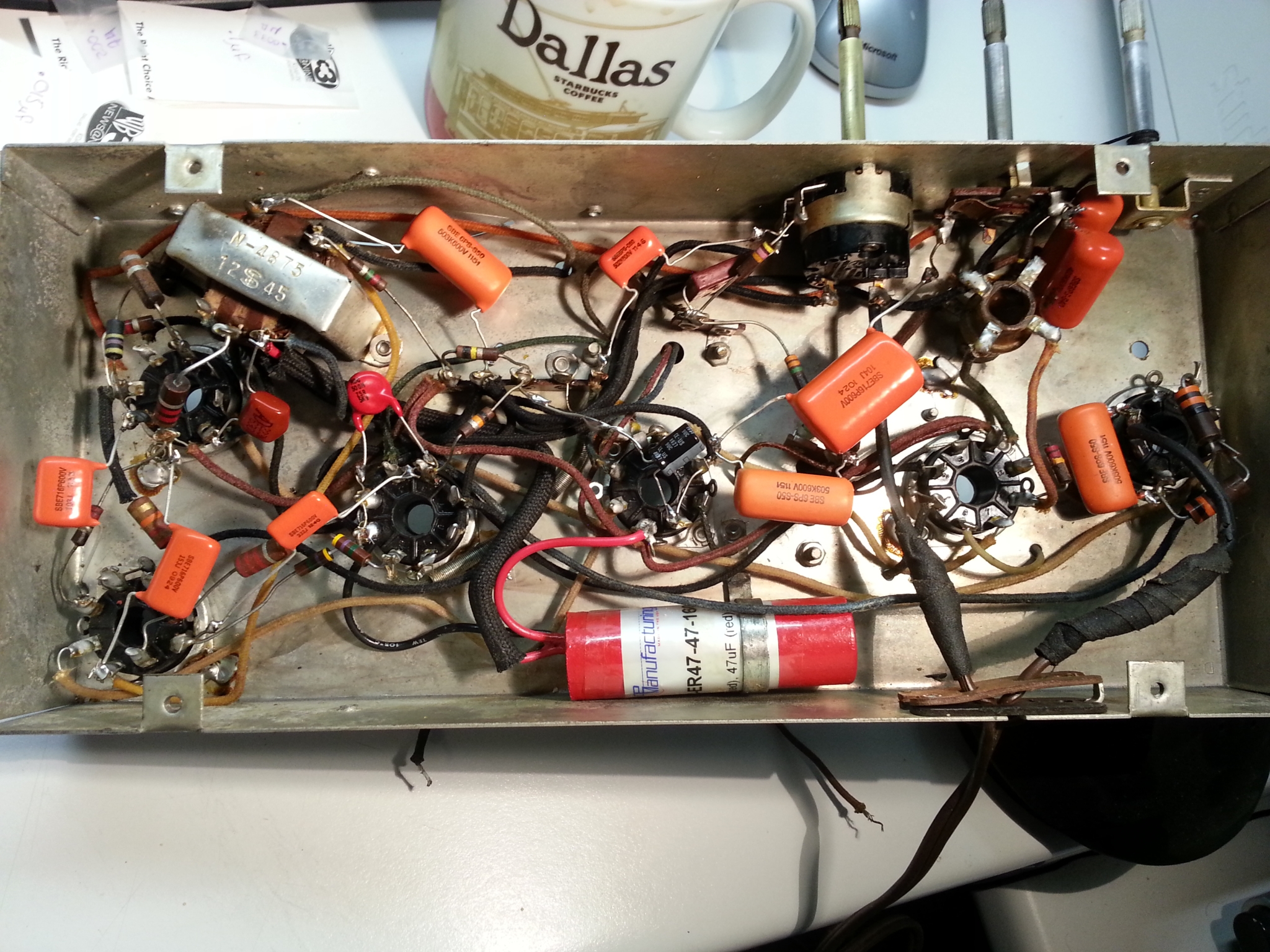
And here it is with new capacitors in place:
Forward to Page 07
Back to Page 05
Back to the Table of Contents

Leave a Reply
You must be logged in to post a comment.