Vintage 1946 Sonora AM Radio Restoration – 14 – Dial Scale position sensor for the MP3 Player
Vintage 1946 SONORA AM RADIO RESTO-MOD PROJECT
Dial Scale position sensor for the MP3 Player:
In the Past few days I have been really busy on getting some things done to the radio. First off, I made some changes to the wiring in the radio by first making one of the blades wider on the power plug to turn it into a polarized plug. Then I changed the wiring in the radio itself to route the hot side.of the power through the on/off switch. This will prevent the chassis from ever becoming a “Hot” chassis and will help ensure that anyone that is around the radio while it is plugged in will not live a shorter life due to electrocution! 😉 It amazes me that things were done that way back then simply to keep any extra noise from the hot wire from bleeding into the radio while it is playing! I guess they figured if you touched the wrong thing and killed yourself it was your fault! 😉
After that, I began work on the MP3 player! I soldered some headers to the MP3 shield, plugged it into the Arduino UNO micro-controller, loaded up the Arduino software and installed the software libraries to make it do its thing! After a bit of troubleshooting, it was working as expected. So it was time to add the potentiometer to the circuit and start programming.
Once I had the potentiometer working and sending a signal to one of the Analog pins on the Arduino, I created some functions to play specific stations based on the position of the potentiometer. Music will be sent based on a random number generator so it will always be played in a different order. Then I added in some code to play some period specific commercials that I ran across on the internet and downloaded. A commercial will now be played in between songs about once every 10 minutes or so. 😉 So with all of that working as it should, all I have left to do with that part is get all the music converted to the proper format and naming convention, then load it up to the SD card.
So… I then turned my attention to making a pulley that will be mounted to the potentiometer, which will then be mounted to the radio with a small bracket in a place where the dial cord can be routed around this new pulley as well. I had to break out the spreadsheet and create a few formulas to calculate the proper diameter for this new pulley.
The tuning knob currently makes 3.5 revolutions from start to stop and this turns the tuning capacitor a half a turn. So basically a 7 to 1 ratio. The potentiometer has a full travel of 3/4ths of a revolution so the ratio for it to the tuning knob is 7 to 1.5. Using this the rpm and diameters of the tuning knob shaft (.25 inches) and rpm of the potentiometer, I was able to calculate the diameter needed for the new potentiometer pulley at about 1.17 inches.
Now, since it is a bit difficult to just run out an buy small dial cord pulleys in any size you want, I knew I would be machining my own custom pulley for this application. And thanks my son’s experimenting with his own backyard aluminum foundry, I had a chunk of aluminum that would work perfectly for this!
So I started to work on the aluminum on the mill to get a milled flat surface on both sides of the aluminum plate. One I had it milled flat and down in thickness a bit, I marked circle and drilled some holes around the perimeter of the circle to cut a disc out of it.
I then drilled a hole in the center of the disc, mounted it to bolt, then chucked it up in the mini lathe to machine it into a perfect circular disc.
The next step was to use the lathe to machine the disc into a pulley of the proper diameter and add a grove that the dial cord can ride in! This took a little time but it turned out great! Then I used two aluminum strips to make a clamp mount to mount the potentiometer with the new pulley and mounted it all to the radio. After that it was just a matter of cutting a longer piece of dial cord and routing it around the new pulley. Works like a charm!
Here are some photos taken of some of the things mentioned above:
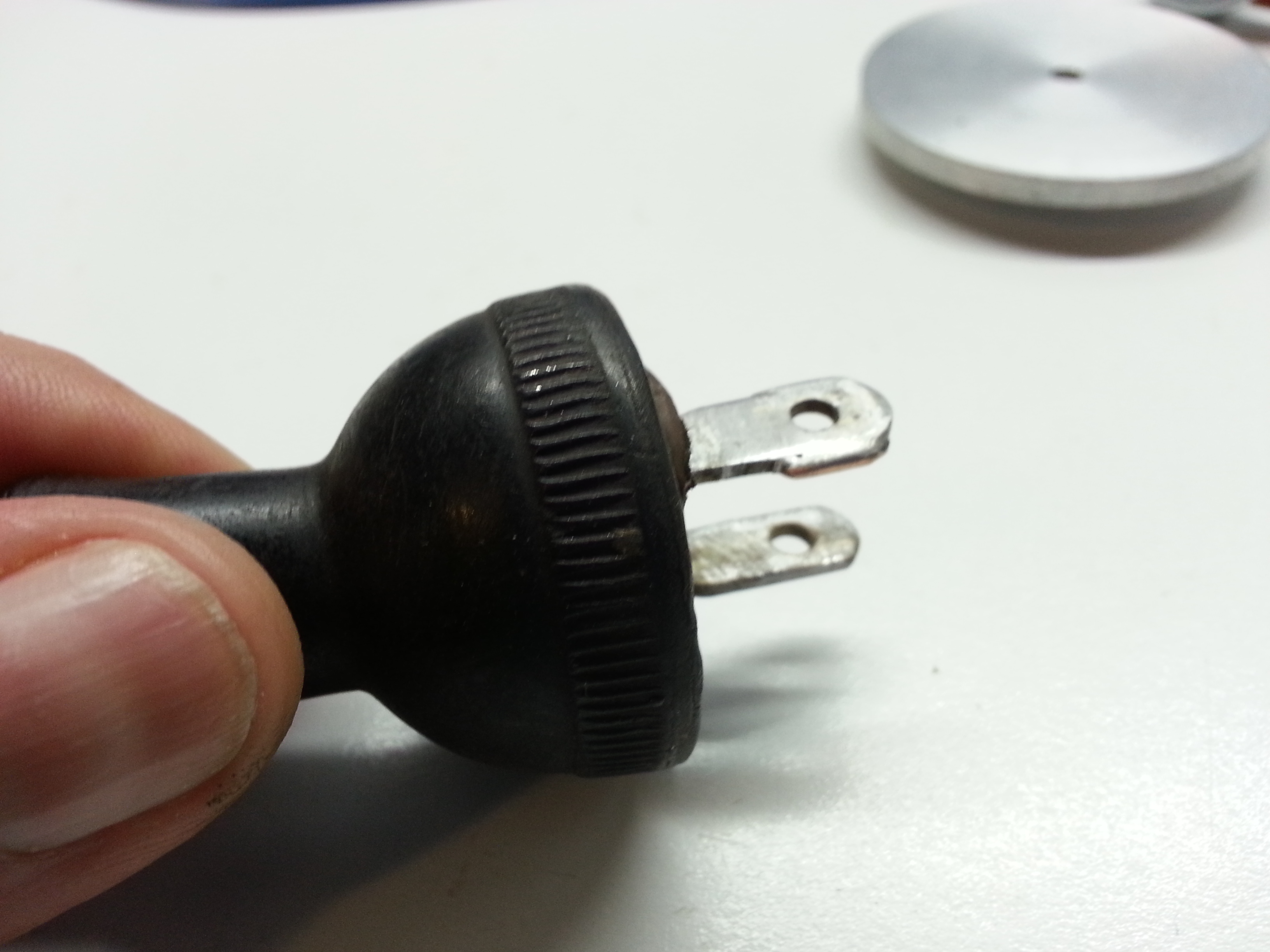
Here is a shot of the power plug after soldering a piece of component lead to the blade to widen it and turn it into a polarized plug.
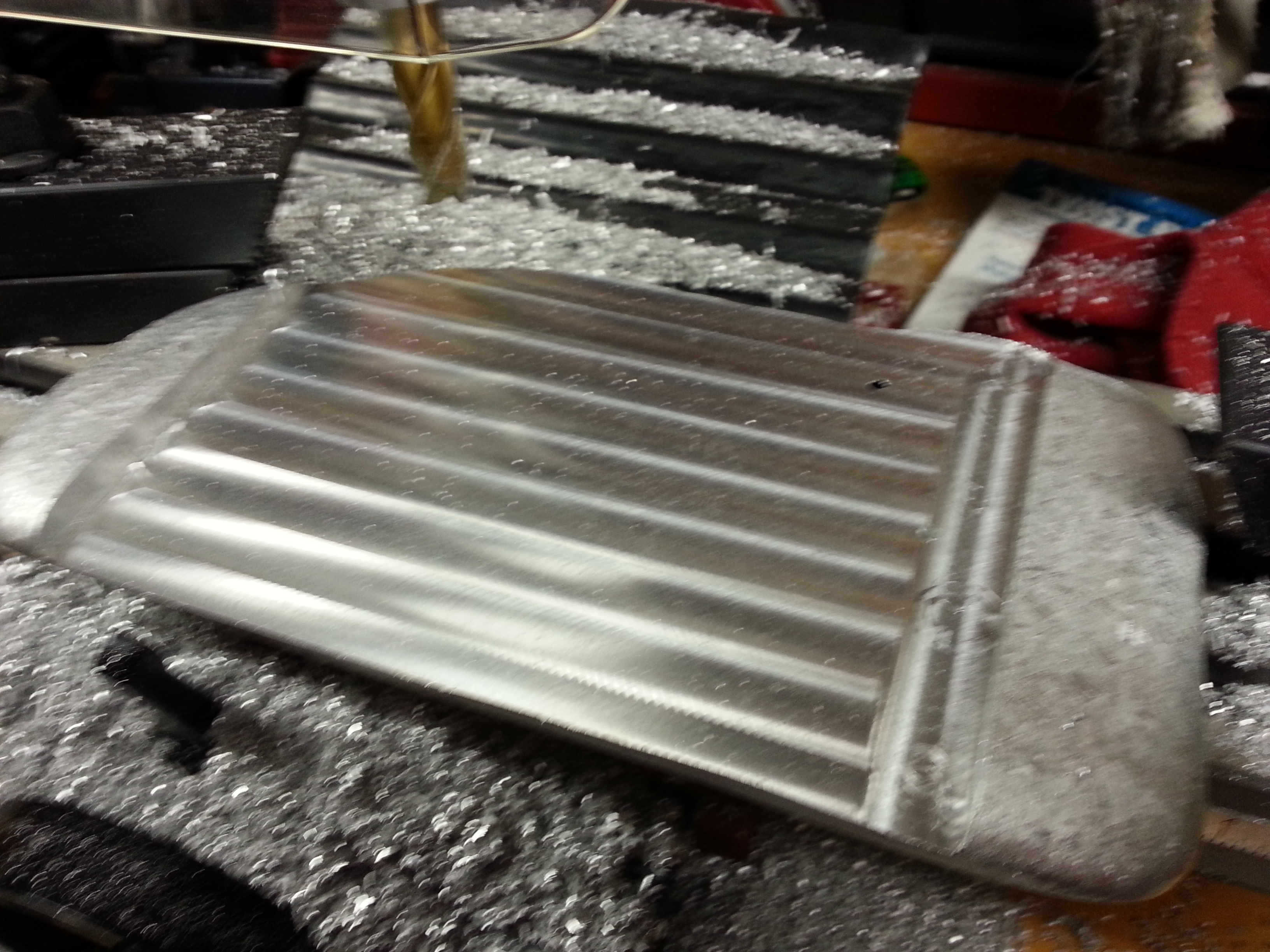
Here is a shot of the chunk of aluminum after milling it down to a flat surface:
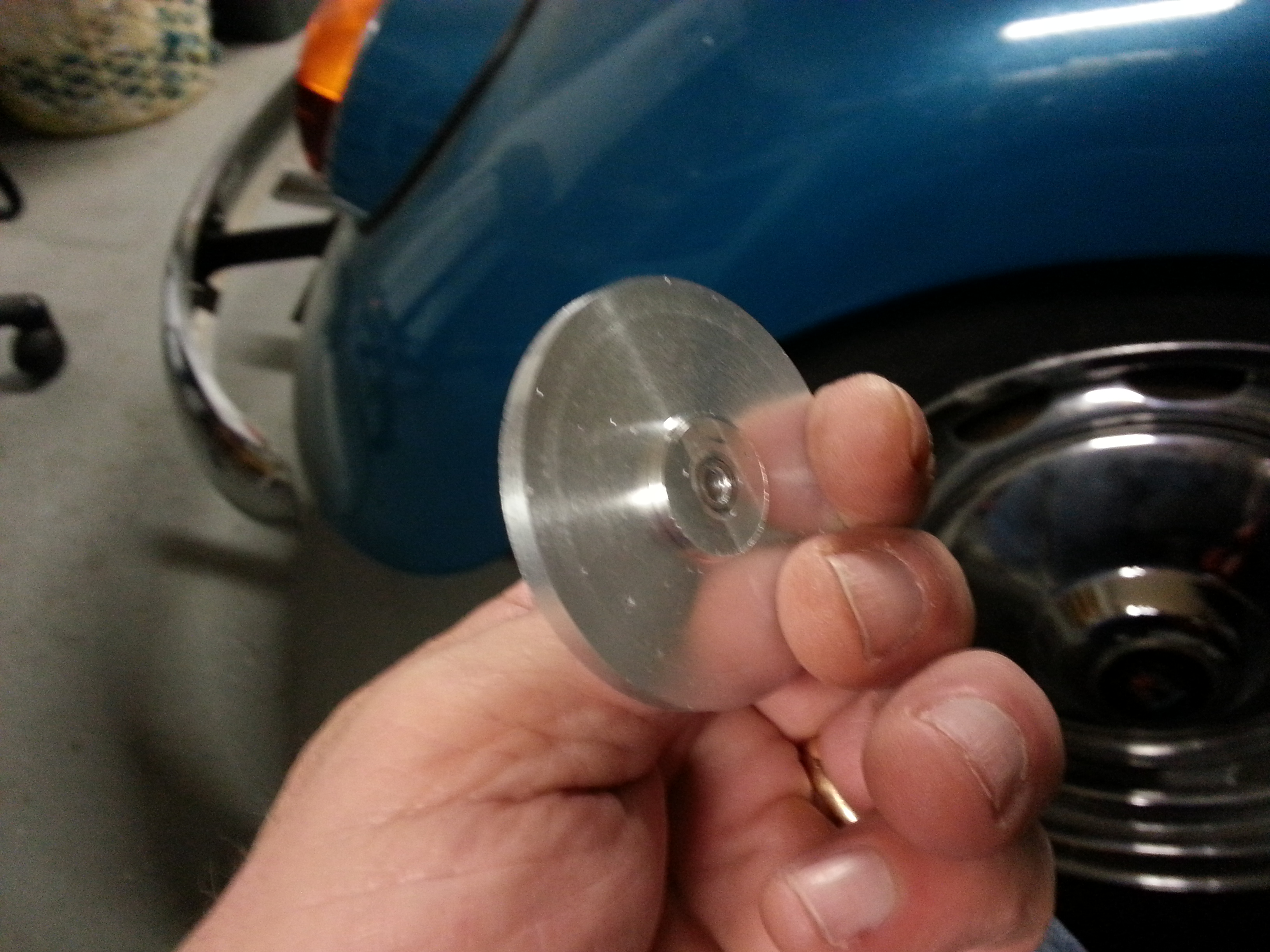
After machining the blank down on the lathe, here is the disk that will ultimately become the pulley:
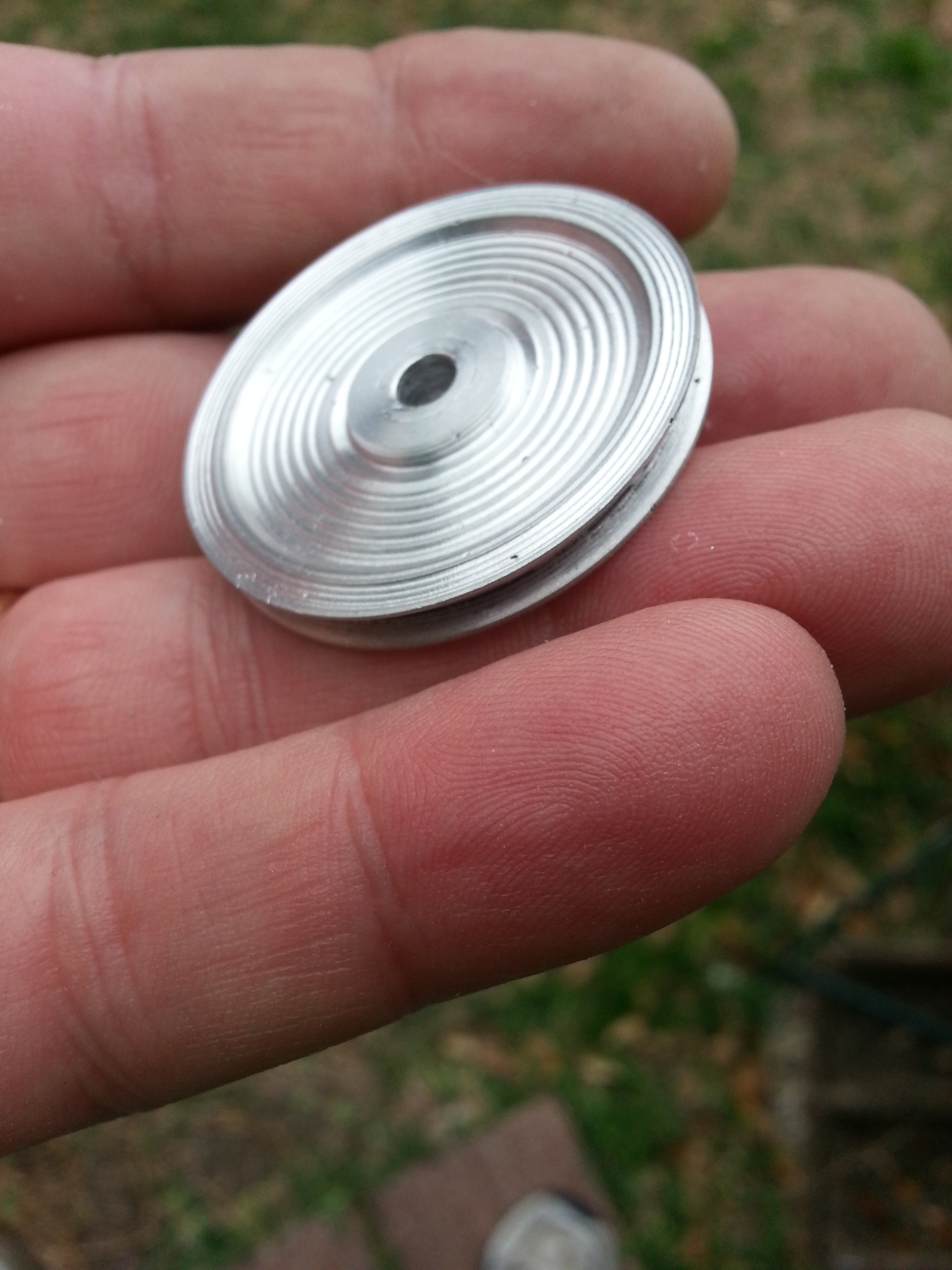
And here is the final pulley:
Here is a video clip of the mounted Pulley and Potentiometer that will give dial positioning to the Arduino board. Note that the mount for this is totally non-destructive to the original radio.
Here is a video clip taken while machining the aluminum blank on the lathe to make the pulley.
Forward to Page 15
Back to Page 13
Back to the Table of Contents

Leave a Reply
You must be logged in to post a comment.